1. Content
This design guide will introduce uPowerTek’s constant current LED driver in different aspects, including its features, strength and how the NFC programmable LED driver works.
2. Introduction of uPowerTek
uPowerTek is a high-tech company which has been dedicated in high quality and intelligent LED drivers for several years. The headquarter including sales, R&D and logistics is located in Binjiang District, Hangzhou, which is a famous high-tech zone in China. The team focus on quality, performance, and solving customer problems.

3. Product Features
3.1 Great Surge Protection
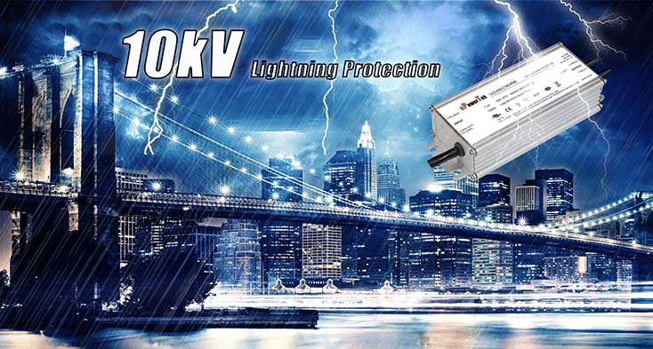
Surge protection plays key role for the reliability of LED drivers, especially for outdoor usage. The BLD product series offer a standard 10kV protection level for common mode (Line/Neutral to Ground) and 4kV or 6kV for differential mode (Line to Neutral) according to IEC61000-4-5, while most of the players in the market is doing 4kV or 6kV for common mode only. Large surge protection devices like MOV and GDT should be used, and also unique designs are utilized to make sure the total size of the driver is compact.

3.2 High Lifetime and Reliability
3.2.1 Lifetime
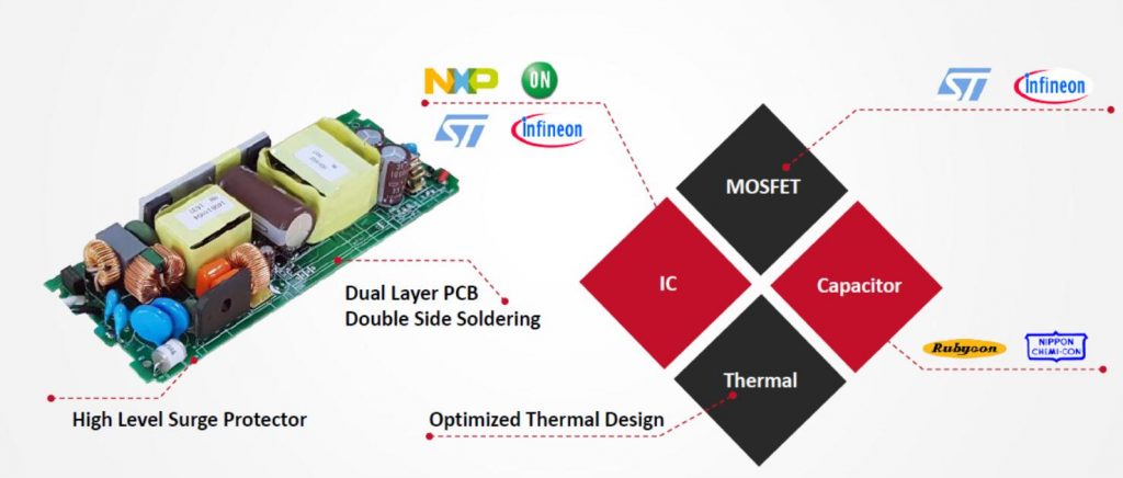
Long lifetime is one of the key advantages LED lighting offers compared to traditional lighting thus greatly reduces the cost of maintenance and other indirect expenses. LED driver is the weakest link for luminaires while the electrolytic capacitors in LED driver is the shortest brick. Japanese high quality and long life capacitors are used in the key positions of the internal circuitry to ensure life. And efficiency and thermal management are also very important to life. We use high efficiency circuitry and aluminum product enclosure to improve lifetime. So the standard lifetime offered is 100khours@Tc =75℃(Tc is the driver case temperature at Tcmax point). The reason we are able to offer so large life time is not only because 12khous capacitors from either NCC or Rubycon are used, but also the thermal design of the whole driver is optimized by internal heatsinks and external aluminum housing. And full potting provides great thermal environment and waterproof.

3.2.2 Reliability
Reliability is affected by design margins, component quality, thermal management, power loss of the whole design and MTBF is usually calculated to evaluate the reliability. Scientists developed models to evaluate the MTBF of whole electrical systems and the most famous one is from MIL-HDBK-217. And the test result from that model is normally very conservative. We offer the calculated MTBF value of no less than 300khours@Tc=75℃.
3.3 Water Resistant
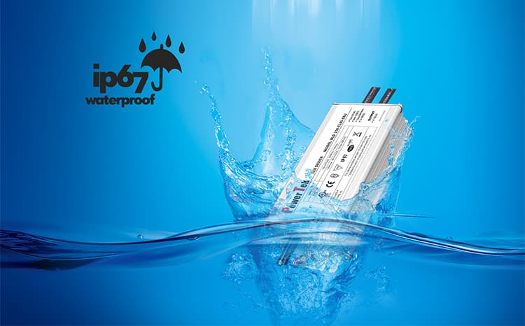
The waterproof level of BLD series can reach IP67, which means that it can be used for outdoor applications, such as LED street light.
3.4 High PF and Low THD with Wide Load Range
The PF (power factor) of a power supply is a ratio of the real power to apparent power of the power consumed by the supply. It is expressed either as a number between 0 and 1 or as a percentage between 0 and 100%.
THD is a measurement of the harmonic distortion present and is defined as the ratio of the sum of the powers of all harmonic components to the power of the fundamental frequency. THD is used to characterize the linearity of audio systems and the power quality of electric power systems. In power systems, lower THD means reduction in peak currents, heating, emissions, and core loss in motors.
Both Energy Star and DLC (Design Lights Consortium) have clear regulation for PF value which has to be >0.9 and DLC also regulates THD should be <20%. And good LED driver design makes sure that the driver works within the regulations in a very wide load range so that the light engineers can use it easily.
uPowerTek LED driver can works at 60%-100% load, for some models, it is around 40%-100%, which is extremely wide. Below is some typical curves of PF and THD.
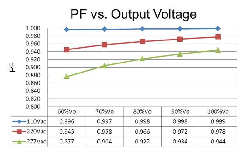
Figure 3 PF Curve
3.5 +/-2% Output Accuracy
As we know that LED light output is generally proportional to the driving current, so to make a light system have uniform light output by different light fixtures, we have to make sure that the driver output currents are consistent with one another. Now most of the LED driver current accuracy is +/-5%, which seems to be good enough for most of the un-dimmable applications, however, if the lights are dimmed down to 10%, for example a non-uniquely designed 700mA driver is down to 10%, 70mA, look at the accuracy of the 70mA, you will see some are 90mA, some are 60mA. Imagine your system is driven by those heavily non-uniform output currents. For human eyes, the dimmed down light difference is more easily to be perceived.

uPowerTek provides the partners with +/-2% accuracy LED driver, and the more important feature is that it also provide very high accuracy in the dimming mode


Figure 4 Measured Light and Perceived Light
3.6 NFC Programmable Functions
3.6.1 Output Current
The output current of traditional LED driver is fixed before shipment, users are not able to adjust the output current value. However, different luminaires require different output current values, which means that factory needs to stock many kinds of driver models to meet the market demand. Obviously, this will extend the lead time and un-flexible. uPowerTek developed programmable LED drivers which can be programmed passively by end users or LED factories. So this design decreases LED driver models and shorten the lead time.

Video introduction of uPowerTek NFC programmable LED driver
Users need to use the NFC programmer and a computer to program the output current, open the software and set the output current, put the NFC programmer close to the LED driver, then the output curent will be changed. Further on, an Android app on any NFC supporting cellphone will be used to replace the programmer.
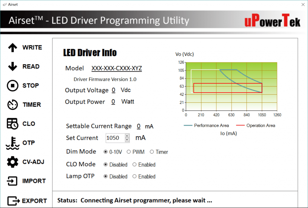
Figure 6 NFC Programming Software Interface
3.6.2 Time Dimming
Besides programming output current, users can also set the time dimming profiles by using the programmer and programming software. The software allows users to write 6 dimming stages into the driver, which can meet most of the requirements. Considering the different lights on time on summer and winter, the LED driver can be written into two different time profiles, the summer profile and winter profile, the driver can switch to the other profile automatically based on the seasonal changes.

3.6.3 Luminaire NTC Thermal Protection (Lamp OTP)
The luminaire is protected by lowering down the driving current when it is overheated. There are two ways to set the luminaire thermal protection scheme. One is by factory setting which means that the current foldback scheme is fixed in the firmware before delivery from factory, and the other is that by NFC Airset user interface the users can set schemes according to different situation which is more flexible and suggested.


3.6.4 CLO (Constant Lumen Output)
This is a function for the luminaire to compensate the depreciation of luminous flux and to avoid excess lighting at the beginning of the installation’s service life. The output current of driver can be customized to be increasing slightly during the life time.
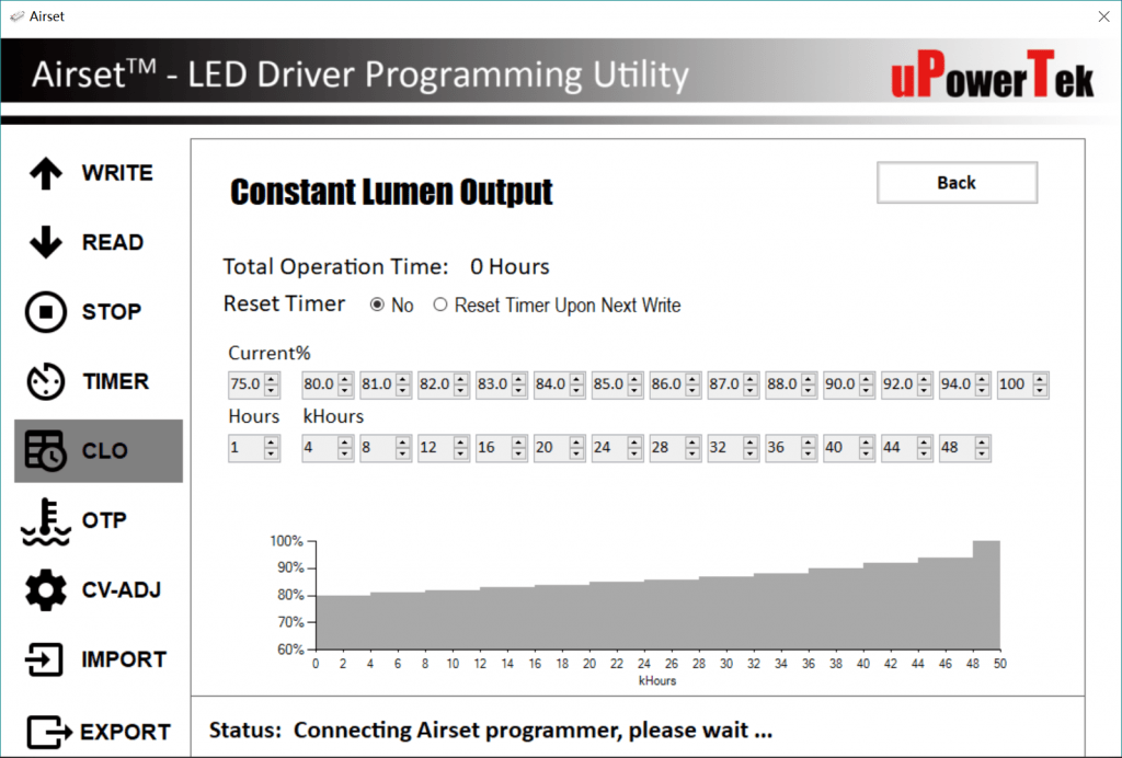
3.7 Dimming and Dim off
3.7.1 0-10V/PWM/Time Dimming
The default dimming method of the cable dimming is 0-10V, which is also the most common way to dim. It is specified by technical standards IEC 60929 Annex E. And since PWM signal dimming has different standards in different global areas, the users may have to contact with our sales to make sure of the correct PWM dimming scheme. The fundamental dimming scheme is as below:

3.7.2 DALI Dimming
Digital Addressable Lighting Interface (DALI) is a trademark for network-based systems that control lighting in building automation. The underlying technology was established by a consortium of lighting equipment manufacturers as a successor for 0-10 V lighting control systems, and DALI is specified by technical standards IEC 62386. Our drivers are designed to be compatible with DALI protocol.
 3.7.3 Dim off
The drivers are designed to be able to turn off with AC connected through control signals. And dim off mode is also called standby mode during which all the components go into the off mode except the auxiliary power and MCU waiting for wakeup signals. The luminaire designers should keep the standby power as low as possible.
3.8 12V Auxiliary
The driver has a 12V auxiliary power for intelligent controllers like motion, daylight sensors and fans, and this saves an extra AC/DC power supply for luminaire designers. The output capability is up to 300mA, higher than other players in this industry .
3.9 Certifications and Ratings
3.9.1 UL Class P
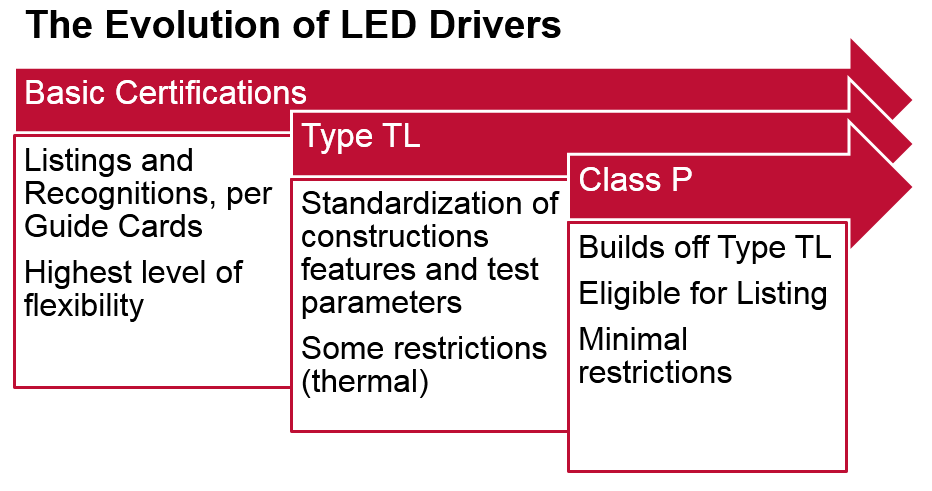
Class P LED driver is a new UL certification which is launched for better LED driver replacement and quality from Mar.2016. The difference of Class P driver compared to traditional or type TL driver is that class P driver is UL listed rather than recognized with type TL and also it is with thermal protection which is able to cut off the main power train of the driver. So it provides more safety to the environment. The figure below is from UL training slides.
3.9.2 ENEC
All our drivers are ENEC and CB certified.
ENEC is the high quality European Mark for electrical products that demonstrates compliance with European standards (EN). European Certification Bodies in the electrical sector have opened the European ENEC Mark to all electrical product sectors. Testing takes place in independent ENEC approved Testing Laboratories worldwide, and in approved Manufacturers’ Laboratories.
ENEC means safety in Europe, and all signatories of the ENEC Mark Scheme actively support its commitment to the highest safety levels.
3.9.3 SELV and Class II
All the products with less than 120Vdc output no matter constant current or constant voltage drivers will be SELV rated. The SELV output driver simplifies the luminaire especially the LED module design since SELV is regarded as a safe source however it increases insulation protection level and of course the difficulty of driver design.
In Europe there are a lot of grid does not contain ground connection. Class II LED driver does not need enclosure grounding to make sure of the insulation and safety. Class II LED driver needs all the conductor inside the driver to be dual or reinforced insulated to outside. We offer the products with Class II input.
3.10 Aluminum Case with Potting
To make sure of good lifetime and reliability, good LED driver designs are using the expensive aluminum enclosure to reduce the thermal resistance from inside to the surface, however increases the cost. Also the fins designed at the sides or top of the enclosures helps with heat dissipation. And good heat co-efficient potting material does the similar job and provides good waterproof for internal components.
3.11 -55C Operation
There are more and more LED street light projects in some extremely cold area where the ambient can be as low as -55℃. However, most of the LED drivers in the market can only works in -40℃. uPowerTek’s owns the patent of -55℃ cold start LED driver. Now 50-150W drivers are able to support the operation.
3.12 Input Voltage Protection
Input voltage protection is not the same as surge protection though they look quite similar. Input voltage protection is usually for protecting drivers from the long lasting but not very high voltage which able to destroy the driver if unprotected. If the input wires are wrong connected or there is unstable electricity grid, input over voltage will happen. Thus we offer 420Vac maximum input drivers with protection threshold of 320Vac. And this will be a different model compared to our standard so please contact with our sales people for ordering details.
I guess you would like to learn more about our products, please click here.

